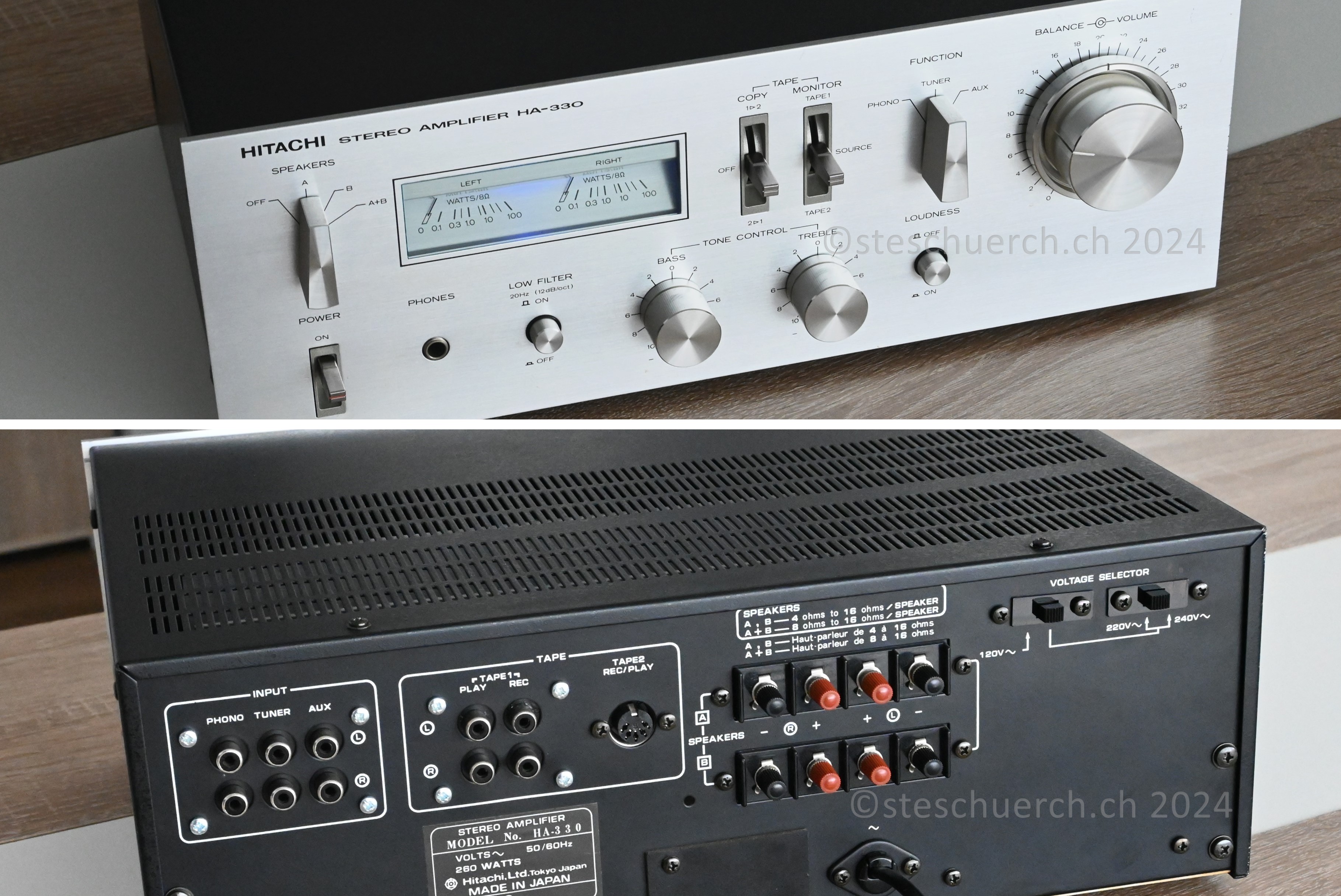
Hitachi HA-330 Stereo Amplifier (1977)
State of preservation and error analysis

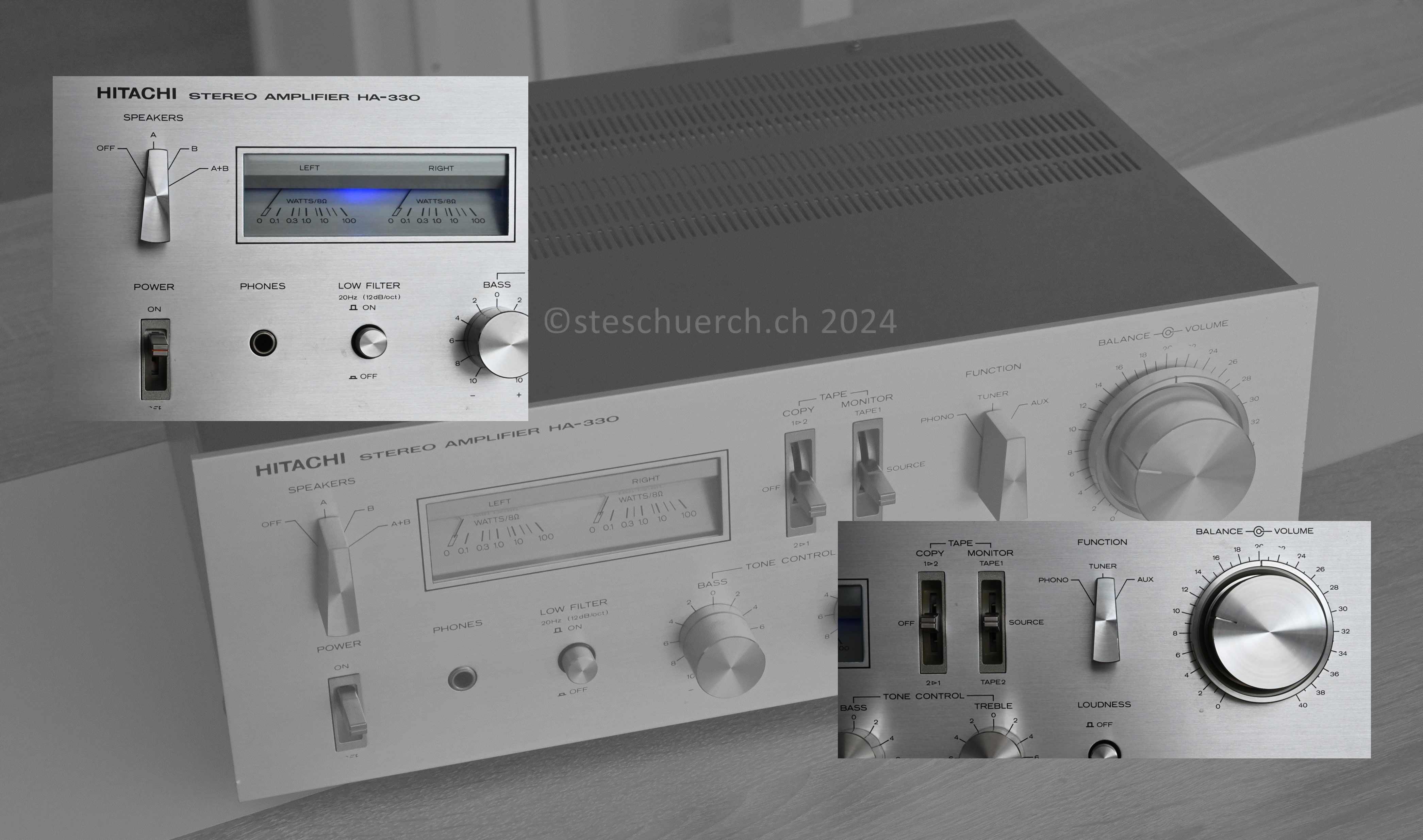
A stereo amplifier from the 70s, which is in good condition.
There are no defects on the front and just needs some cleaning.
On the back, the RCA connectors for tape are dented and the housing
has a dent. Here it seems to have had mechanical impact/stress.
The power cable plug is not original and was once replaced with
a 3-pole one, which is not optimal.
Repair and revision recording
After a closer examination, some defects and deficiencies were revealed, which are listed below:
- Clean and treat contacts of potentiometers and switches to prevent oxidation
- Repair the dent in the housing on the back.
- Fasten RCA connectors and repair broken PCB
- Remove fabric hoses in the electronics
- Check the ESR of capacitors and replace the electrolytic capacitors that visually show oxidation points.
- Replace the thermal paste on the output stage transistors and check the contacts and insulating disks on the heat sink.
- Install a new power cable and new power clamp
- Lighting from the VU meter displays has no function - change the lamp
- Alignment and testing of the protective circuits according to the service manual
- Stress test of the LF amplifier
- Clean the outside of the housing
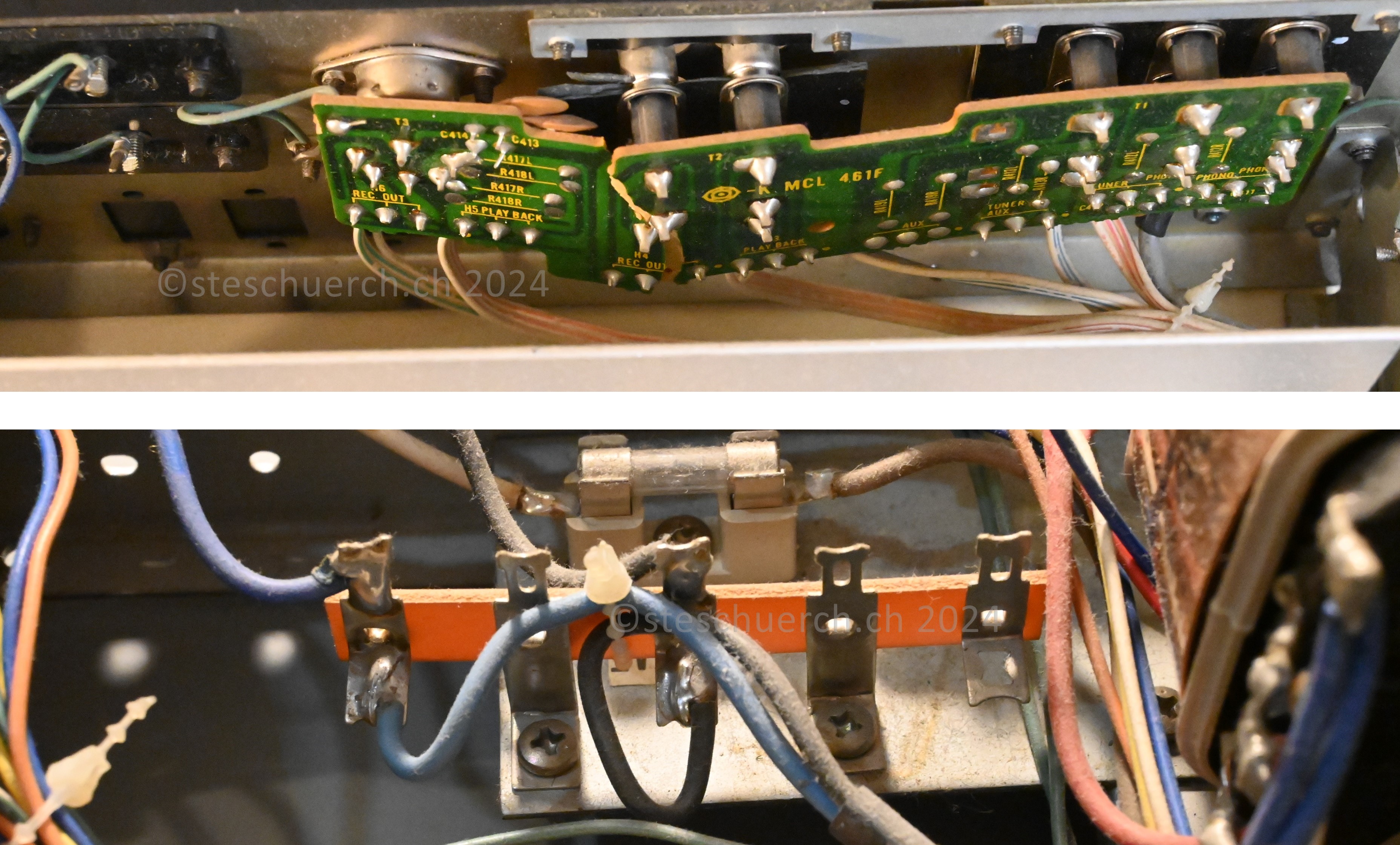
After opening the case, the extent of the damage on the back is
quickly visible. Here the PCB of the RCA connections must be glued
and the interrupted conductor tracks must be reconnected. From
today's perspective, the primary-side power connection terminal
is not very safe and must be replaced by an insulated luster terminal.
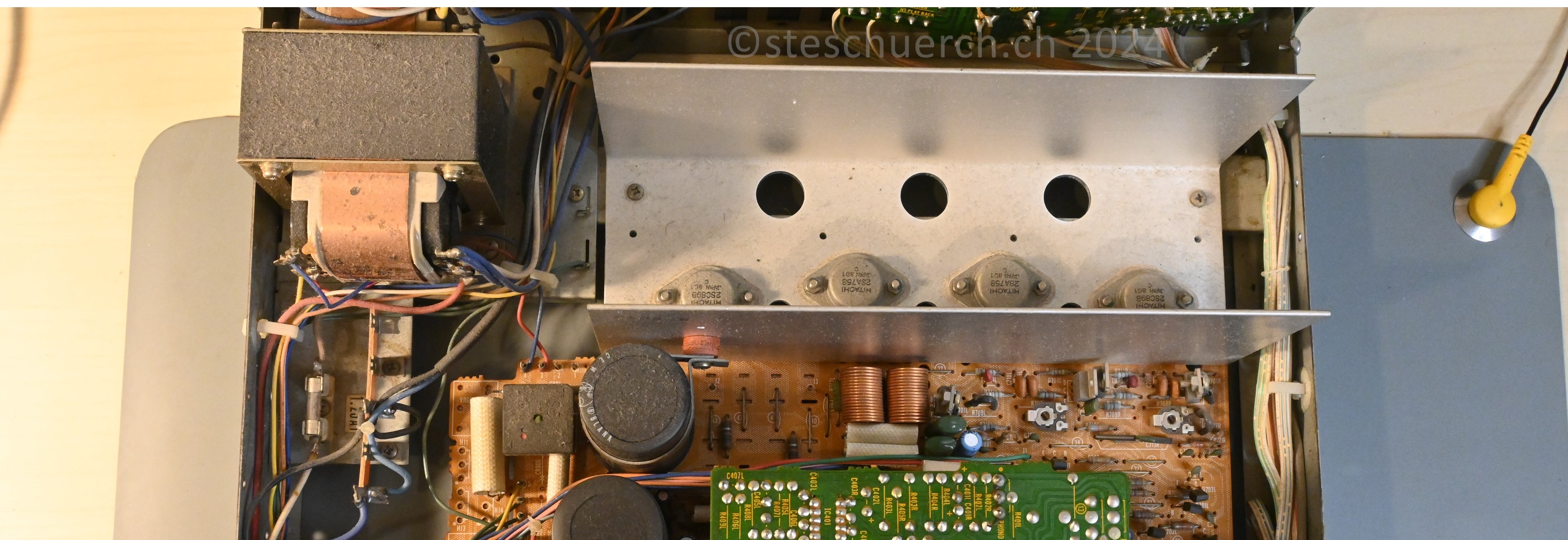
The device has a large layer of dust on the inside that needs to be
removed. The electronics appear undamaged and are visually in good
condition. As was common practice in the 1970s, fabric hoses were
attached around the larger resistors. These now have a slightly
sticky surface, which can only have a negative effect and produce
electrical leakage currents via the resistors. -Because of this problem,
these are all removed, and this also ensures better heat dissipation
from the components.
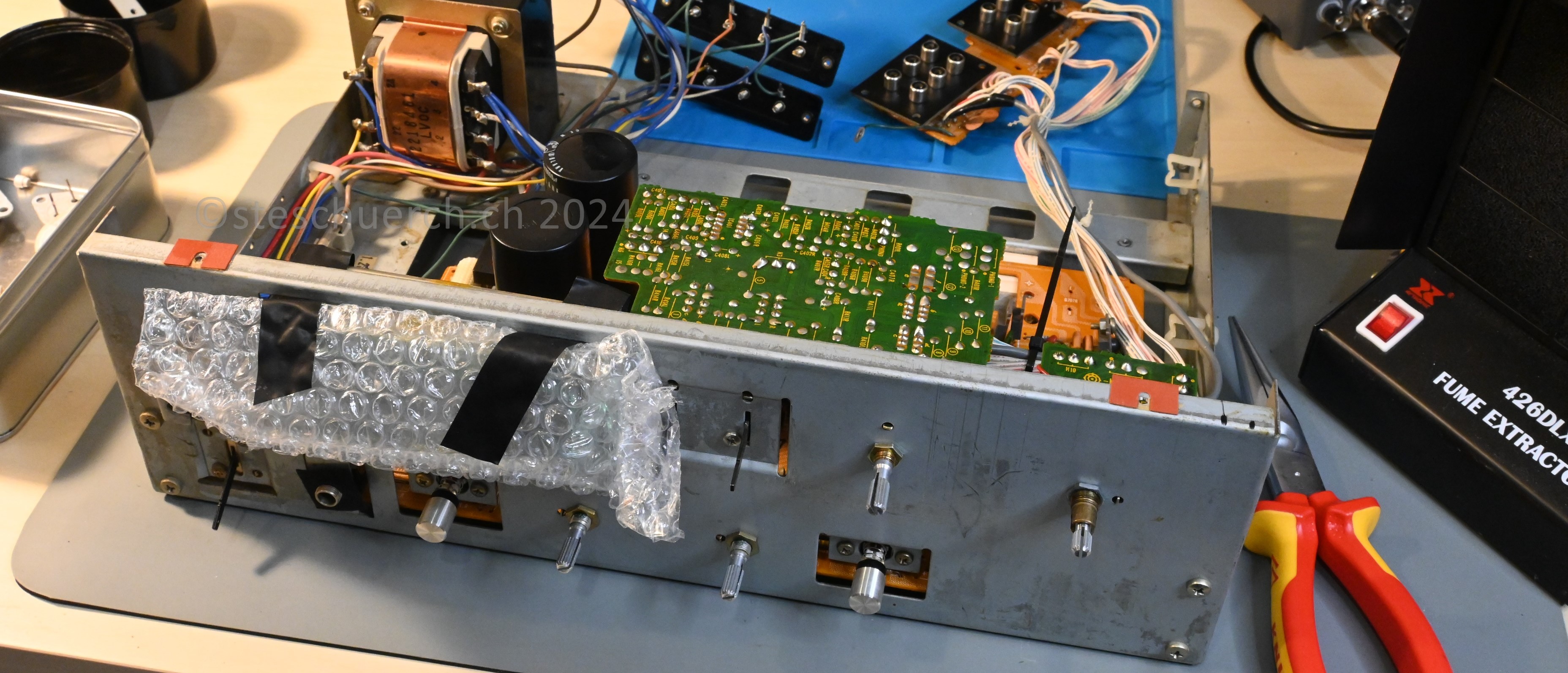
The device is almost completely disassembled. As protection during the
inspection work, the VU meter Plexiglas housing was wrapped in
protective film. The output stage transistors are desoldered and
the heatsink is removed and cleaned.
Troubleshooting and restoration
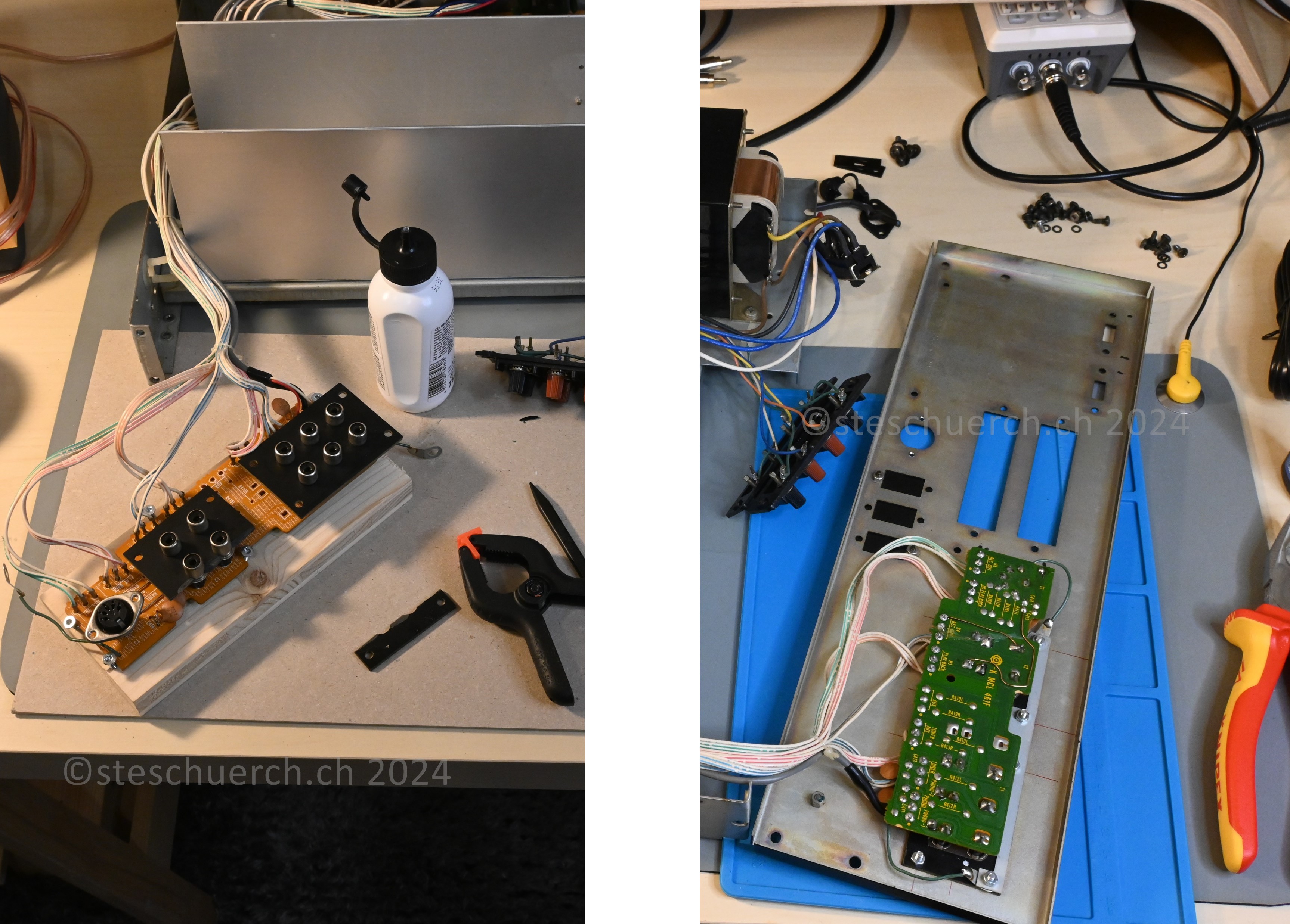
The broken connection PCB is glued together with wood glue. For this
purpose, a device had to be made so that after the glue was applied,
the broken points of the PCB could be pressed together evenly and
with enough force over several hours so that the glue creates the
best bond. The electronics are then screwed back onto the housing.
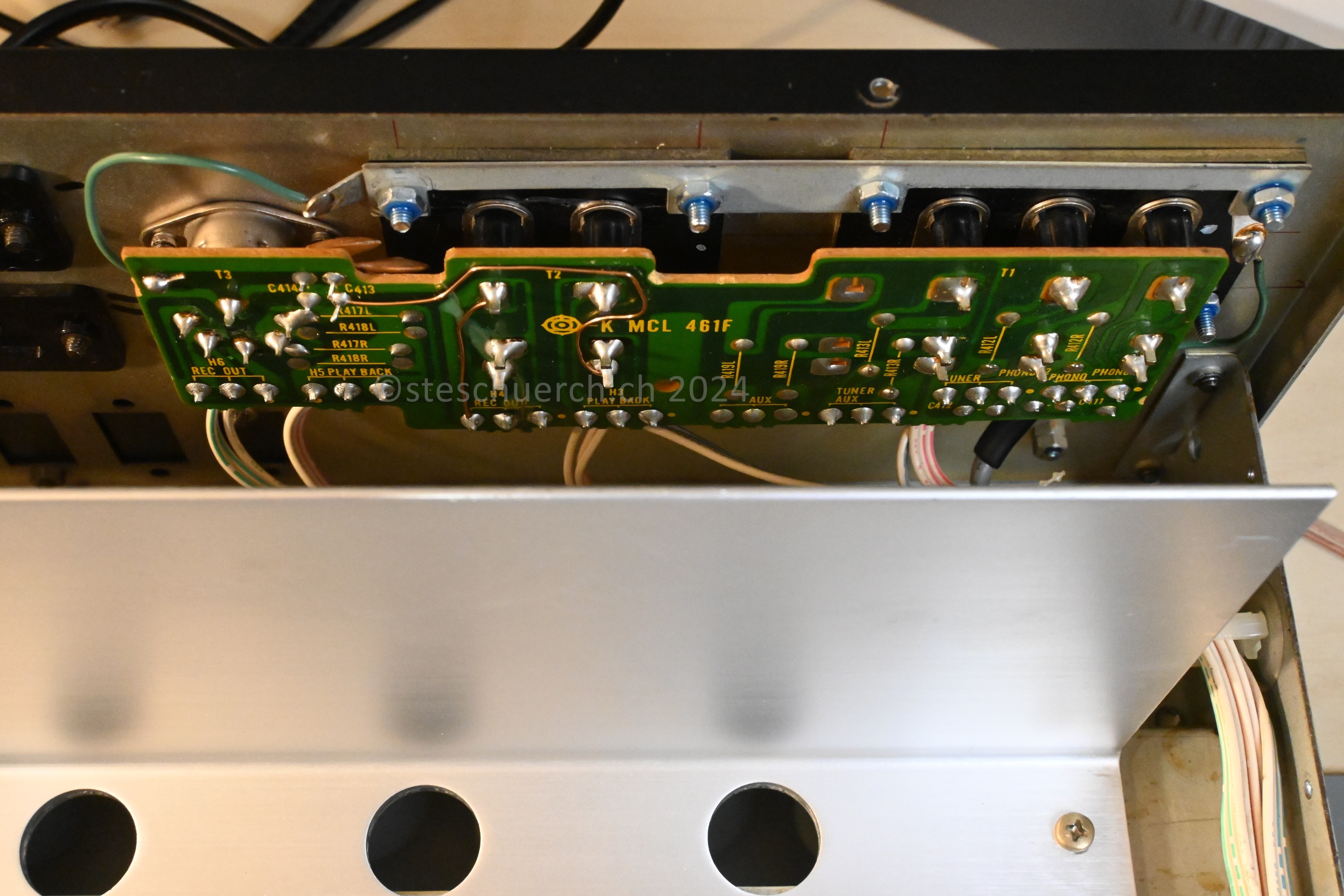
The connection PCB panel was originally screwed to the housing with
an insufficient number of screws. That's probably why there was a
break, because e.g. when connecting a RCA cable, a leverage force
could always act on the PCB. It is not known why screws and drilling
were saved here. - This problem has now been resolved and additional
holes have been made in the housing for proper screw connection.
Final result
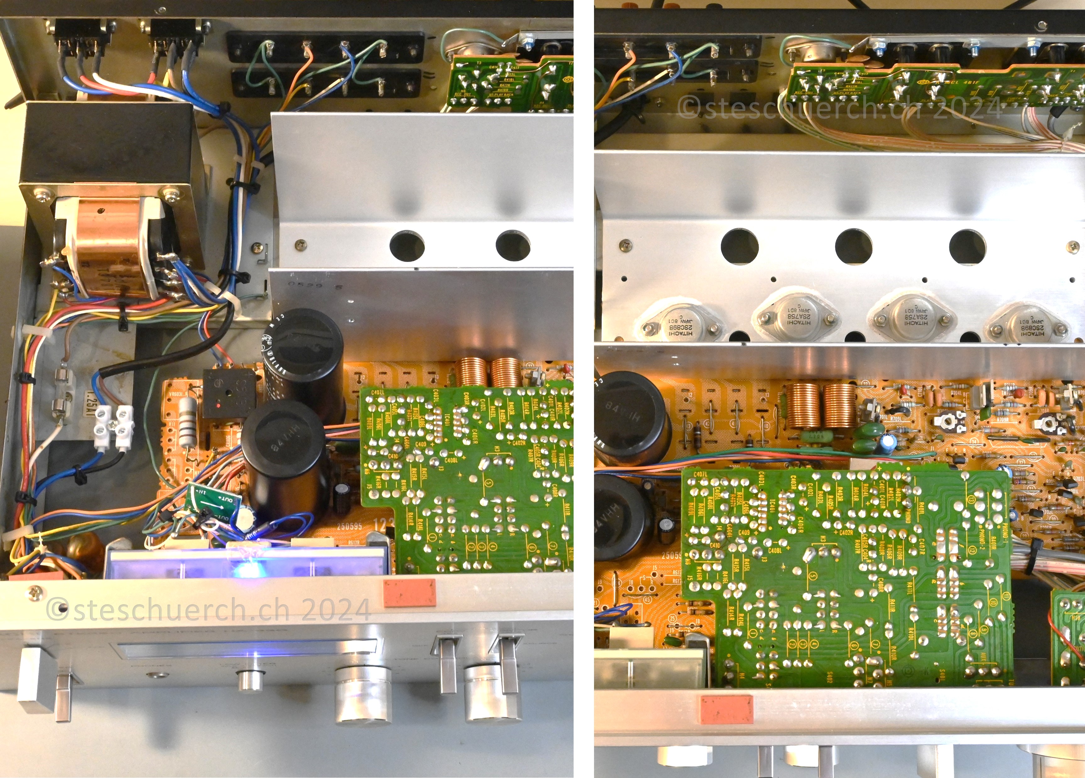
The heatsink and the transistors now appear in new splendor.
The electronics work perfectly and the bias voltages are set perfectly.
On the left of the picture you can see the newly installed terminal
for the primary tap to the power switch and subsequent transformer.
New cable ties were attached around the wiring of the strands.
The resistors are freed from the fabric tubes. The display lighting
was replaced by an LED; due to the lamp diameter, this worked best
mechanically. To do this, a stepdown converter had to be installed
and a series resistor for the LED, with which it now illuminates
the VU displays at a pleasant and not too intrusively modern light intensity.
In the end, an audio source and speakers were connected to the
amplifier using the audio connections on the back. A high volume
can be achieved thanks to the approximately 50 W maximum power
per channel. The power amplifiers passed the stress test at high
volume for several minutes without any problems. The heatsink has
reached normal temperature after playing music for a long time and
the transistors can be assessed as functioning without any defects.
This means that a well-preserved Hitachi stereo amplifier from the
70s can continue to serve for many years and impress the listener
with great sound and decent music performance.